 |
MPLAB® Harmony Graphics Suite
|
|
MPLAB® Harmony Graphics Suite
|
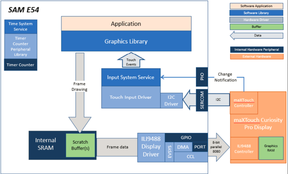
The legato_cooker application uses the Legato Graphics Library to render graphics to the display. The Legato graphics library draws the updated sections of the frame to an internal scratch buffer. The contents of the scratch buffer are used to update the contents of the LCD display. Via the ILI9488 display driver, boosted with a combination of DMA and CCL peripherals, scratch buffer data is transferred out to the ILI9488 controller via 8-bit parallel in 8080 mode.
The application also features user touch input through the integrated touch screen on the display panel. Touch input from the touch controller goes through the I2C port, and the Input System Service acquires the touch input information from the Touch and I2C drivers. The Input System Service sends touch events to the Graphics Library, which processes these events and updates the frame data accordingly.
This configuration runs on the SAM E54 Curiosity Ultra board with a 24-bit passthrough GFX interface card and a maXTouch Curiosity Pro display. The maXTouch Curiosity Pro display has an ILI9488 display controller that is connected to the SAM E54 thru the port/GPIO peripheral using an 8-bit 8080/Parallel interface, boosted with a combination of DMA and CCL peripherals. The Legato graphics library draws the updated sections of the frame to an internal scratch buffer which is used by the ILI9488 display driver to update the ILI9488 display controller.
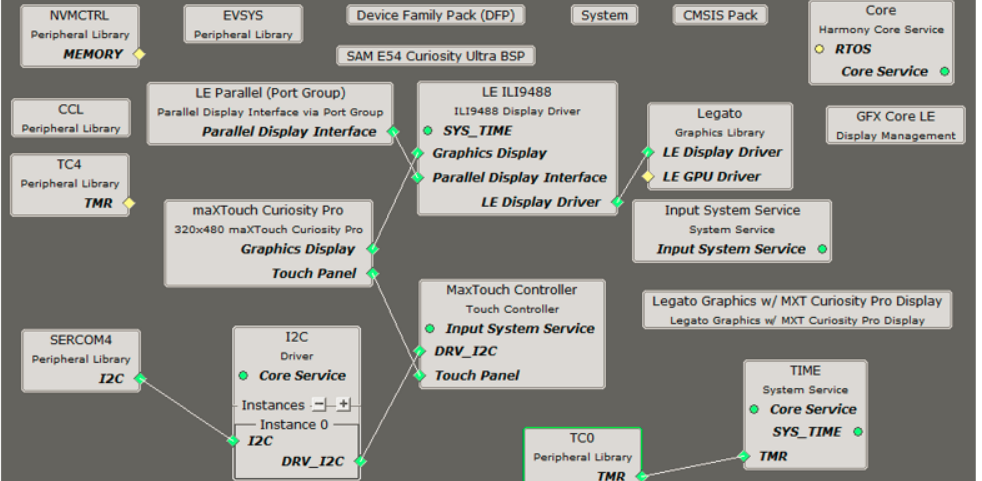
The Project Graph diagram shows the Harmony components that are included in this application. Lines between components are drawn to satisfy components that depend on a capability that another component provides.
For the DMA-CCL boosted setup, components TC4, CCL needs to be added.
Additional components to support QSPI and SST26 needs to be added and connected manually.
Some of these components are fine with default settings, while other require some changes. The following is a list of all the components that required custom settings
The parent directory for this application is gfx_apps/legato_cooker. To build this application, use MPLAB X IDE to open the gfx_apps/legato_cooker/firmware/legato_ck_e54_cult_cpro_parallel.X project file.
The following table lists configuration properties:
| Project Name | BSP Used | Graphics Template Used | Description |
|---|---|---|---|
| legato_ck_e54_cult_cpro_parallel.X | SAM E54 Curiosity Ultra BSP | Legato Graphics w/ Xplained Pro Display | SAM E54 Curiosity Ultra w/ maXTouch Xplained Pro display via 8-bit parallel interface |
**_NOTE:_** This application may contain custom code that is marked by the comments // START OF CUSTOM CODE ... and // END OF CUSTOM CODE. When using the MPLAB Harmony Configurator to regenerate the application code, use the "ALL" merging strategy and do not remove or replace the custom code.
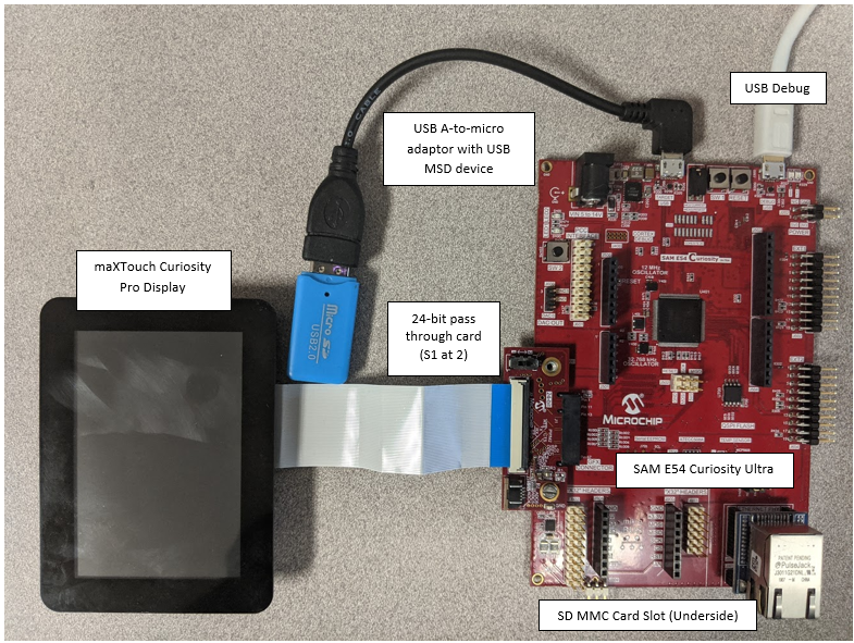
Configure the hardware as follows:
The final hardware setup should be:
Power up the board by connecting the power adapter to power connector or a powered USB cable to the DEBUG USB port on the board.
The application first boots to an alpha-blend Splash Screen.

Once the Splash Screen animation completes, the application boots to a Basic Main Screen. The color gamut for the Basic Main Screen is purposely muted

Touch Cook, Reheat, Bake or Broil button to initial a cooking progress sequence

Touch the RGB ellipse button on the upper right to switch to the Color Screen. The Color Screen is designed to transition from the Basic Screen with some simple animation.
 1.8.18