 |
MPLAB® Harmony Graphics Suite
|
|
MPLAB® Harmony Graphics Suite
|
The application uses the Legato Graphics library to render text on a label widget, an image and a user-interactive button to the screen. Touching the button on the screen will show the button being pressed.
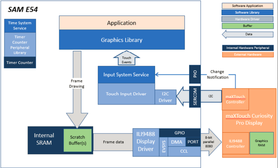
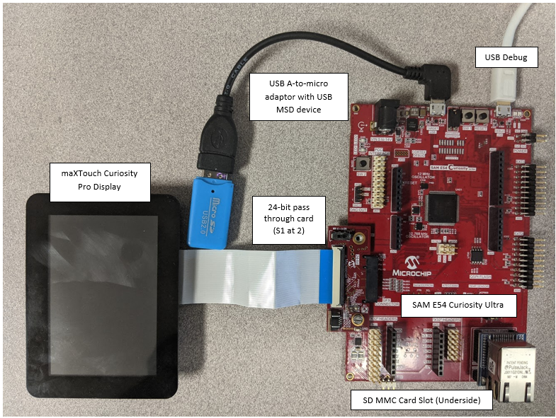
This configuration runs on the SAM E54 Curiosity Ultra board with a 24-bit passthrough GFX interface card and a maXTouch Curiosity Pro display. The maXTouch Curiosity Pro display has an ILI9488 display controller that is connected to the SAM E54 thru the port/GPIO peripheral using an 8-bit 8080/Parallel interface. The Legato graphics library draws the updated sections of the frame to an internal scratch buffer which is used by the ILI9488 display driver to update the ILI9488 display controller.
The ILI9488 display driver uses the DMA to drive command and data values out to the parallel PORT IO. Every time the DMA is done sending a word/byte, it uses the Event System (EVSYS) to send an event to the CCL peripheral. When the CCL receives the event, it generates an active low pulse that drives the write enable pin to the ILI9488 display controller. This combination of DMA-EVSYS-CCL works like an external bus interface for writing parallel data out thru the PORT pins. The other control signals DC# and CS# are controlled by the CPU in GPIO mode.
User touch input on the display panel is received thru the PCAP capacitive touch controller, which sends a notification to the Touch Input Driver. The Touch Input Driver reads the touch information over I2C and sends the touch event to the Graphics Library thru the Input System Service. The block diagrams below show the various software and hardware blocks used in this application:
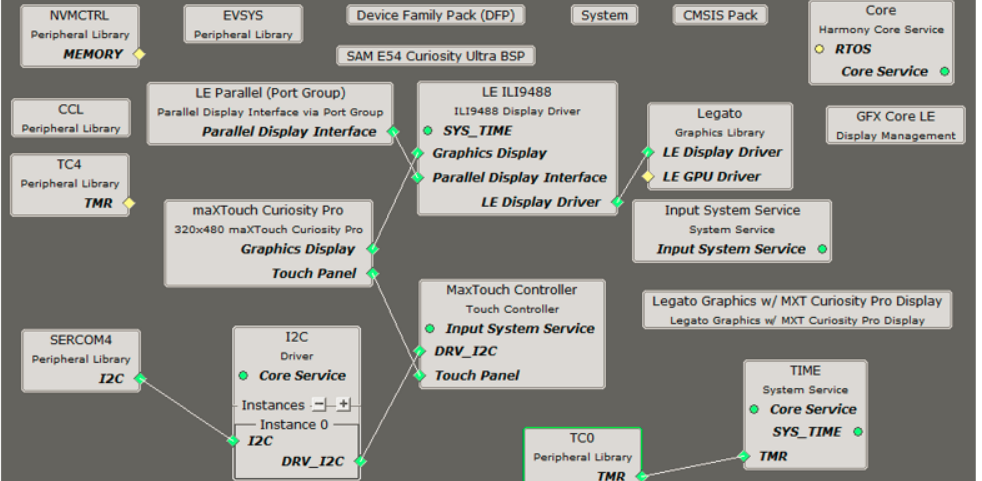
Adding the �SAM E54 Curiosity Ultra BSP� and �Legato Graphics w/ MXT Curiosity Pro Display� Graphics Template component into the project graph.
This will automatically add the components needed for a graphics project and resolve their dependencies. It will also configure the pins needed to drive the external peripherals like the display and the touch controller.
For the DMA-CCL boosted setup, components TC4, CCL needs to be added.
Additional components to support File System, MSD Client Driver, USB Full Speed Driver, USB Host Layer, SDMMC, SDHC1, QSPI and SST26 needs to be added and connected manually.
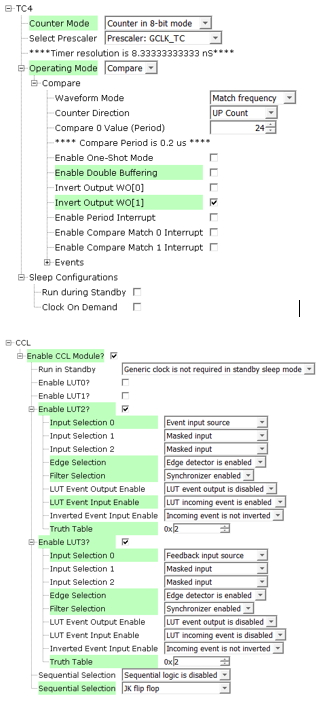
Some of these components are fine with default settings, while other require some changes. The following is a list of all the components that required custom settings.
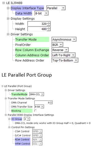
To setup the CCL to clock the pixel data, make sure PB09 is set to CCL_OUT2

Instead of write strobe, make sure PB17 is setup as RSDC instead

The parent directory for this application is gfx_apps/legato_monitor. To build this application, use MPLAB X IDE to open the gfx_apps/legato_monitor/firmware/legato_qs_e54_cult_cpro_parallel.X project file.
The following table lists configuration properties:
| Project Name | BSP Used | Graphics Template Used | Description |
|---|---|---|---|
| legato_qs_e54_cult_cpro_parallel.X | SAM E54 Curiosity Ultra BSP | Legato Graphics w/ Xplained Pro Display | SAM E54 Curiosity Ultra w/ maXTouch Xplained Pro display via 8-bit parallel interface |
**_NOTE:_** This application may contain custom code that is marked by the comments // START OF CUSTOM CODE ... and // END OF CUSTOM CODE. When using the MPLAB Harmony Configurator to regenerate the application code, use the "ALL" merging strategy and do not remove or replace the custom code.
Configure the hardware as follows:
The final hardware setup should be:
Power up the board by connecting the power adapter to power connector or a powered USB cable to the DEBUG USB port on the board.
When power-on is successful, the demonstration will display a similar menu to that shown in the following figure (different configurations may have slight variation in the screen aspect ratio):
 1.8.18