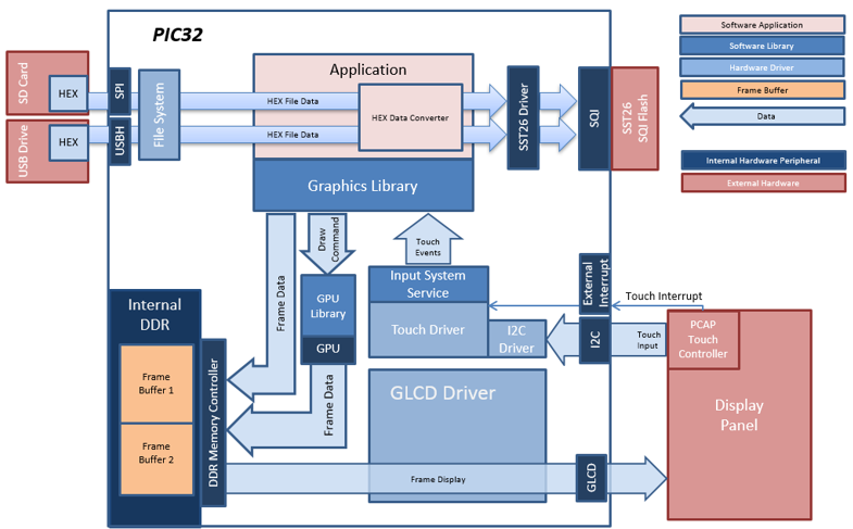
The aria_flash application uses the USB and SD card file systems in MPLAB Harmony and the SPI and USB drivers to scan the MSD for a .hex file with resources and reads them sector by sector and programs the external non-volatile SQI memory. The Graphics Library is used to render graphics to the display. Using the MZ DA’s internal display controller (GLCD) to continuously transfers frame data from the frame buffer out to the LCD display.
The application also features user touch input through the integrated touch screen on the display panel. Touch input from the touch controller goes through the I2C port, and the Input System Service acquires the touch input information from the Touch and I2C drivers. The Input System Service sends touch events to the Graphics Library, which processes these events and updates the frame data accordingly.
For this configuration, the application uses the Graphics Library to render graphics to the display. The Graphics library passes draw commands into the GPU Library, which in turn draws the widgets and images to the write frame buffer stored in the DDR memory. Via the DDR2 Memory Controller, the GLCD display controller peripheral continuously transfers frame data from the read frame buffer onto the LCD display. The buffers are swapped when the Graphics Library has finished writing to the write buffer.
User touch input on the display panel is received thru the PCAP capacitive touch controller, which sends a notification to the Touch Input Driver. The Touch Input Driver reads the touch information over I2C and sends the touch event to the Graphics Library thru the Input System Service.
The USB peripheral is setup in MSD Host mode with the File System service support. It scans for a file named SQI.hex when a USB MSD device is connected.
The SD Card reader on the MEB-II is connected to the PIC32MZ DA starter kit via the SPI peripheral with the File System service support. It scans for a file named SQI.hex when an SD card MSD device is connected.
The application reads the hex data from the file and decodes it with a hex decoder into binary data. The binary is written to external non-volatile memory via the SQI peripheral configured with the SST26 driver.
• Aria Graphics Library
• Input system service and touch driver
• Time system service, timer-counter peripheral library and driver
• GLCD internal LCD display driver
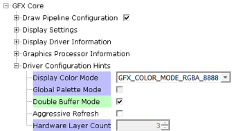
• 32-bit RGBA8888 color depth (single-layered double buffering)
• GPU library with accelerated draw commands
• EBI peripheral library and driver
• I2C peripheral library and driver
• SST26 SQI driver
• USB MSD driver (Host Mode)
• SD Card driver (supported via SPI)
• File System
• Images and Fonts for user interface stored in internal flash
The Project Graph diagram below shows the Harmony components that are included in this application. Lines between components are drawn to satisfy components that depend on a capability that another component provides.
Adding the “PIC32MZ DA Starter Kit BSP” and “Aria Graphics w/ PDA TM4301B Display” Graphics Template component into the project graph will automatically add the components needed for a graphics project and resolve their dependencies. It will also configure the pins needed to drive the display and the touch controller.
For the GFX Core component enable double buffering.
Additional components to support USB, SQI and SD Card needs to be added and connected manually.
Some of these components are fine with default settings, while other require some changes. The following is a list of all the components that required custom settings.
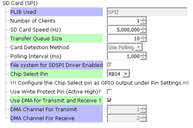
SD Card (SPI) component
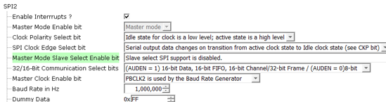
SPI2 component
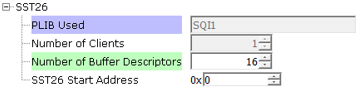
SST26
The SD Card (SPI) driver needs access to a chip select pin. Make sure pin RB14 is set to GPIO (Latch High, Pull Up)

The USB MSD driver in Host mode will require VBUS_AH detection. In the Pin Configuration window, make sure pin RB5 is setup for VBUS_AH

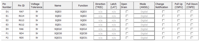
For SQI access, make sure all 7 pins for SQI1 is mapped.
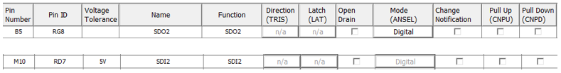
To support the SD card reader with the SPI2 peripheral pins SDI2 and SDO2 needs to be mapped.
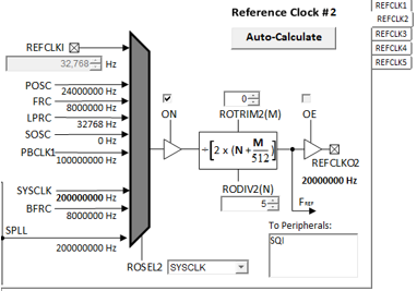
To drive the SQI device, make sure REFCLK2 is setup with RODIV2 set to 5, such that output is 20 MHz
In MPLABX, open the project in gfx_apps\apps\aria_flash\firmware
|
Project Configuration Name |
BSP Used |
Graphics Template Used |
Description |
|
aria_fl_mzda_intddr_sk_meb2_tm4301b.X |
PIC32MZ DA Starter Kit BSP |
Aria Graphics w/ PDA TM4301B Display |
PIC32MZ DA INT DDR Multimedia Expansion Board II with 4.3” WQVGA PCAP Touch display |
 Important! |
This application may contain custom code that is marked by the comments // CUSTOM CODE ... and // END OF CUSTOM CODE. When using the MPLAB Harmony Configurator to regenerate the application code, use the "Prompt Merge For All Differences" merging strategy and do not remove or replace the custom code. |
This section describes how to configure the supported hardware.
On the MEB II, the EBIOE and LCD_PCLK (J9) must be jumpered. A connection establishes the GLCD's pixel clock output timing. The external SRAM memory on the board is disabled. The J9 jumper is located on the bottom of the MEB II board, beneath where the starter kit is plugged into the board. Refer to the following figure for the exact location.
![]()
- Connect the PIC32MZ DA Starter Kit board to the MEB II board
- Power up the board by connecting the power adapter to J3 power connector on the MEB II board or a powered USB cable to the USB DEBUG port on the Starter Kit board
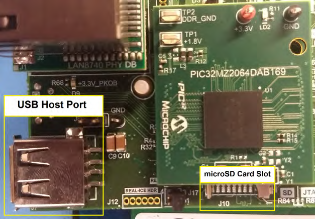
- Use the microSD slot and USB host port on Starter Kit for the media. Refer to the following figure for the location of the ports
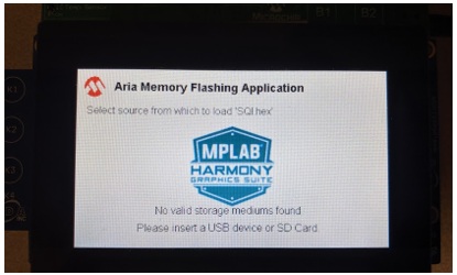
When power-on is successful, without a USB or SD Card MSD device attached, the demonstration will display a screen with the message “No valid storage mediums found. Please insert a USB device or SD Card”:
Connect a USB MSD device or SD card at the slots indicated in the picture.
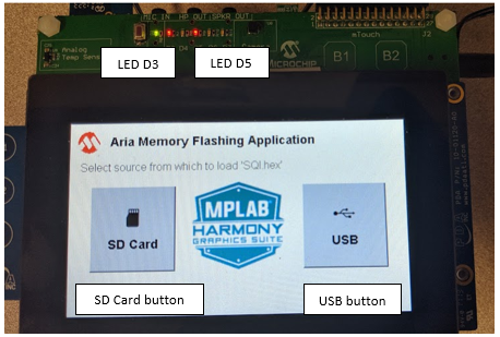
If a valid USB MSD device is connected, the display will show a USB button. LED1 (red on the starter kit) will light up. LED D3 on the MEB-II will also light up.
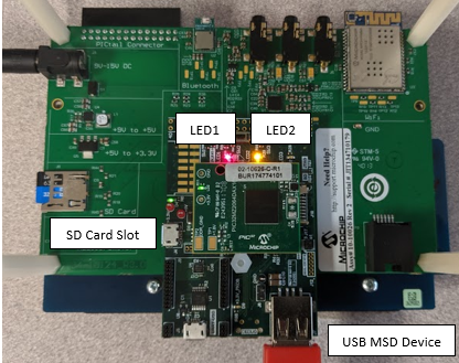
If a valid SD Card device is connected, the display will show a SD Card button. LED2 (yellow on the starter kit) will light up. LED D5 on the MEB-II will also light up.
Make sure the USB or SD Card MSD device has FAT32 file system format and a valid external resources file named precisely ‘SQI.hex’ is copied inside.
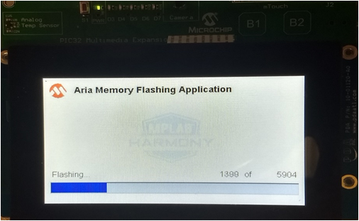
Press and release the USB or the SD card button on-screen. The application will initiate the data transfer on release of the button. Depending on the size of SQI.hex file (greater than 500 kilobytes), the application may freeze with no visual feedback, upwards of 30 seconds. It will then display a progress bar to indicate the transfer. The transfer completes when the progress bar is filled. The application will then display a button with ‘OK’.
|
MPLAB® Harmony Graphics Suite
|