This aria_quickstart configuration runs the Aria Graphics Library in a FreeRTOS environment. The Aria Graphics Library runs as stand-alone task, fully-blocking and waiting for events from external tasks like system service task or the application task. Thread-safe APIs for sending events to the Aria task are provided by the Aria RTOS extension library.
In this configuration, the Aria Graphics library renders the frame to a 32-bit frame buffer in external DDR. The LCDC display controller on the A5D2 is used to drive frame data from DDR to the display. 16-bit RGB565 frame buffer is stored in the internal SRAM.
User touch input on the display panel is received thru the PCAP capacitive touch controller, which sends a notification to the Touch Input Driver. The Touch Input Driver reads the touch information over I2C and sends the touch events to the Aria Graphics Library Task thru the Input System Service Task.
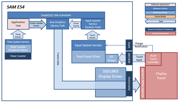
This aria_quickstart configuration runs the Aria Graphics Library on the SAM E54 Xplained Pro board with an external SSD1963 display controller driving a WVGA display running with FreeRTOS. The Aria Graphics Library runs as stand-alone task, fully-blocking and waiting for events from external tasks like system service task or the application task. Thread-safe APIs for sending events to the Aria task are provided by the Aria RTOS extension library
The SSD1963 display controller is used to send the display data and timing to a display. The SSD1963 is connected to the SAM E54 thru the PORT peripheral and GPIOs which are used to send 16-bit parallel data/commands and to bit-bang control signals to the SSD1963 controller, respectively. The frame buffer is stored externally in the SSD1963 controller.
User touch input on the display panel is received thru the PCAP capacitive touch controller, which sends a notification to the Touch Input Driver. The Touch Input Driver reads the touch information over I2C and sends the touch event to the Graphics Library thru the Input System Service.
Demonstration Features
• FreeRTOS and Aria Graphics Library with RTOS extensions
• Input system service and touch driver
• Time system service, timer-counter peripheral library and driver
• SSD1963 display controller driver
• PORT/GPIO peripheral library and driver
• I2C driver
• 16-bit RGB565 color depth support (65535 unique colors)
• JPEG image stored in internal flash
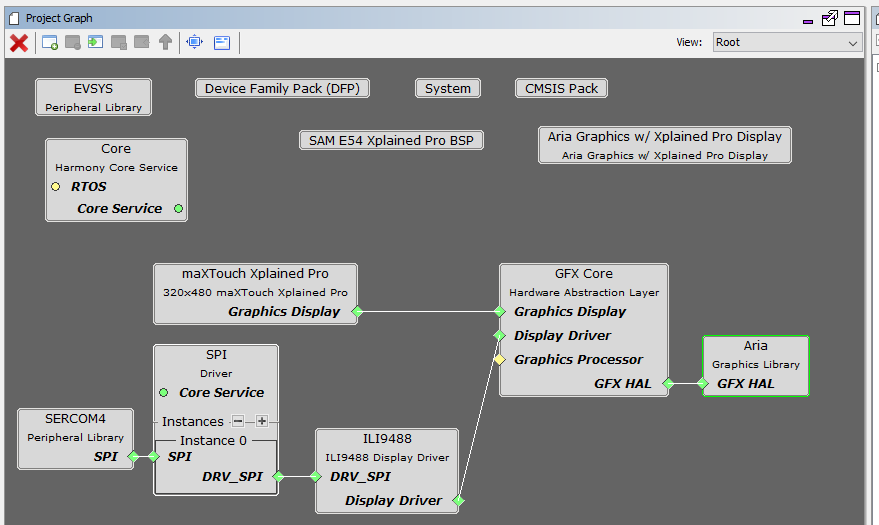
The Project Graph diagram below shows the Harmony components that are included in this application. Lines between components are drawn to satisfy components that depend on a capability that another component provides.
Adding the “SAM E54 Xplained Pro BSP” and “Aria Graphics w/ Xplained Pro Display” Graphics Template component into the project graph will automatically add the components needed for a graphics project and resolve their dependencies. It will also configure the pins needed to drive the external peripherals like the display and the touch controller.
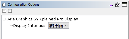
Under the configuration options for the “Aria Graphics w/ Xplained Pro Display” GFX template component, the “Display Interface” is set to “SPI 4-line”.
The parent directory for this application is gfx/apps/aria_quickstart. To build this application, open the gfx/apps/aria_quickstart/firmware/aria_quickstart_e54_xu_tm5000_ssd1963_freertos.X project file.
The following table lists configuration properties:
|
Project Name |
BSP Used |
Graphics Template Used |
Description |
|
aria_quickstart_e54_xu_tm5000_ssd1963_freertos.X |
SAM E54 Xplained Ultra |
Aria Graphics w/ PDA TM5000 Display |
Aria GFX on SAM E70 XULT Board and PDA TM5000 Display, using SSD1963 external controller, with FreeRTOS |
 Important! Important! |
This application may contain custom code that is marked by the comments // START OF CUSTOM CODE ... and // END OF CUSTOM CODE. When using the MPLAB Harmony Configurator to regenerate the application code, use the "ALL" merging strategy and do not remove or replace the custom code. |
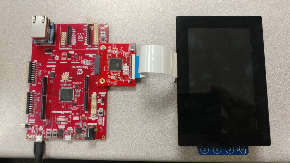
The final setup should be:
When power-on is successful, the demonstration will display a similar menu to that shown in the following figure (different configurations may have slight variation in the screen aspect ratio):
When Make changes. Generate. Run. is touched, the button will toggle with each individual touch.
|
MPLAB® Harmony Graphics Suite
|