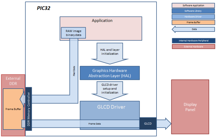
In this configuration, the application calls HAL APIs to initialize the HAL data structures and set up the HAL graphics layers. These API calls translate into Graphics LCD (GLCD) driver set up and initialization calls that configure the GLCD. After the initialization phase, the application transitions into the paint phase where it draws an image to the frame buffer in external DDR. The application uses a HAL API to get the start address of the frame buffer in the DDR and writes the pixel data directly to the frame buffer memory address.
The GLCD hardware peripheral continuously refreshes the display panel with data from the frame buffer and the images are shown on the display.
- Graphics Hardware Abstraction Layer (HAL)
- GLCD Driver
- Enable Use Graphics Stack in MPLAB Harmony Configurator (MHC)
- In MHC, under the Graphics Stack options
- Set Graphics Processor > Select Processor Type to None
- Uncheck Use Harmony Graphics Composer Suite to disable the Aria User Interface Library
- Uncheck Graphics Options > Enable Draw Pipeline
- For the FreeRTOS configuration (e.g., pic32mz_da_sk_intddr_meb2_freertos), set the following in MHC:
- Third Party Libraries > RTOS, enable Use RTOS. Set Select RTOS to FreeRTOS and set RTOS Configuration > Tick Rate (Hz) to “100”
- In Application Configuration > Application 0 Configuration > RTOS Configuration, set Task Priority to “2”, check Use Task Delay and set Task Delay to “10”.
- In Harmony Framework Configuration > RTOS Configuration, set System Task Priority to “2”, check Use System Task Delay and set Task Delay to “10”.
- In Harmony Framework Configuration > Graphics Stack > Use Graphics Stack > Graphics RTOS Configuration, set Run Library Tasks As to Combine with System Tasks.
![]()
The parent directory for this application is gfx_apps/apps/blank_quickstart. To build this application, use MPLABX IDE to open the gfx_apps/apps/blank_quickstart/firmware/blank_qs_mzda_extddr_sk_meb2_wqvga.X project file.
The following table lists configuration properties:
|
Project Name |
BSP Used |
Graphics Template Used |
Description |
|
blank_qs_mzda_extddr_sk_meb2_wqvga |
PIC32MZ DA Starter Kit BSP |
Aria Graphics w/ PDA TM4301B Display |
PIC32MZ Embedded Graphics with External DRAM (DA) Starter Kit, Multimedia Expansion Board II (MEB II) and 4.3” WQVGA (480x272) Display. |
- On the MEB II, the EBIOE and LCD_PCLK (J9) must be jumpered. A connection establishes the GLCD's pixel clock output timing. The external SRAM memory on the board is disabled. The jumper (J9) is available on the bottom side of the MEB II board under the starter kit. The J9 jumper is located on the bottom of the MEB II board, beneath where the starter kit is plugged into the board. Refer to the following image for the exact location.
- Connect the PIC32MZ DA Starter Kit board to the MEB II board.
- Power up the board by connecting the power adapter to J3 power connector on the MEB II board or a powered USB cable to the USB DEBUG port on the Starter Kit board
![]()
Once the board is powered on, the application will run and show the following image on the display panel.
![]()
|
MPLAB® Harmony Graphics Suite
|