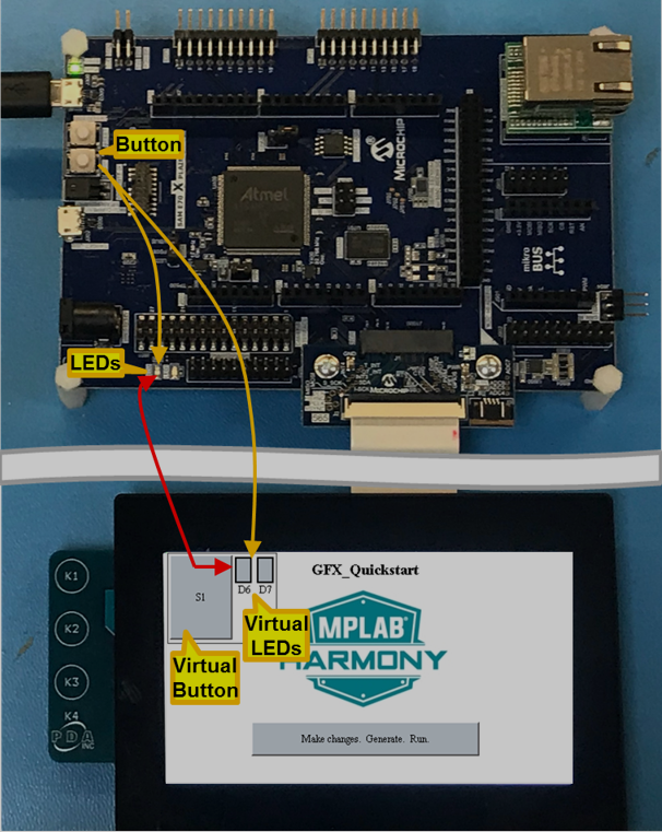
Pressing the board’s button or the screen’s virtual button will turn on the board’s LEDs and the screen’s virtual LEDs. The first part of this tutorial lesson we focus on teaching the application to read the board’s button and control the board’s LEDs. The second part we add the virtual button and virtual LEDs to the screen and connect the board and display together.
Part 1: The steps are as follows:
1. Make a copy of the ./gfx/apps/aria_quickstart folder on your hard drive.
(Located at .\gfx\apps\aria_quickstart\firmware\aria_qs_e70_xu_tm4301b.X)
Then Load the copied aria_quickstart project into the MPLAB.X IDE.
2. Launch the MPLAB Harmony Configurator (MHC):
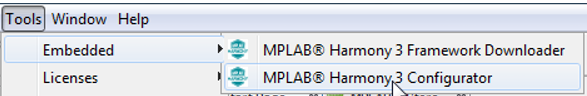
3. Launch the MPLAB Harmony Configurator (MHC):
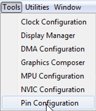
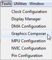
4. From the MHC’s Tools menu launch the Pin Configuration Tool:
5. Verify that the Board Support Package (BSP) has correctly configured the ports attached to the board’s button and LEDs:
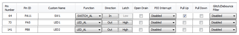
(Note: SW1 is the BSP name for the button on the board.)
If any changes are made to the Pin Table then save the MHC state:
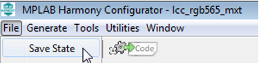
and regenerate the code: 
6. Double click on bsp.h to see what macros are available to control the button and LEDs:
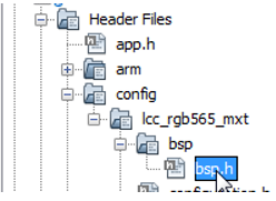
The file contains:
// *****************************************************************************
// *****************************************************************************
// Section: BSP Macros
// *****************************************************************************
// *****************************************************************************
/*** LED Macros for LED1 ***/
#define LED1_Toggle() (PIOA_REGS->PIO_ODSR ^= (1<<5))
#define LED1_On() (PIOA_REGS->PIO_CODR = (1<<5))
#define LED1_Off() (PIOA_REGS->PIO_SODR = (1<<5))
/*** LED Macros for LED2 ***/
#define LED2_Toggle() (PIOB_REGS->PIO_ODSR ^= (1<<8))
#define LED2_On() (PIOB_REGS->PIO_CODR = (1<<8))
#define LED2_Off() (PIOB_REGS->PIO_SODR = (1<<8))
/*** SWITCH Macros for SW1 ***/
#define SW1_Get() ((PIOA_REGS->PIO_PDSR >> 11) & 0x1)
#define SW1_STATE_PRESSED 0
#define SW1_STATE_RELEASED 1
7. Double click on app.c to bring up an editor: 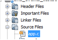
Add a static boolean flag to keep track of the button’s state:
/******************************************************************************
  Function:
    void APP_Tasks ( void )

  Remarks:
    See prototype in app.h.
 */
static bool bS1State;   // Button (Switch 1) state                         //New
static bool bLED_State; // Past LED state                                  //New
static bool bLED_StateNow; // Current LED state based on button state      //New
In APP_Tasks add code to the APP_STATE_SERVICE_TASKS state to poll the button.
        case APP_STATE_SERVICE_TASKS:
        {
            bS1State = !SW1_Get(); // Closed --> grounded                  //New

            bLED_StateNow = bS1State; // Closed button => LEDs on.         //New
            if ( bLED_State != bLED_StateNow )                             //New
            {// LED state has changed                                      //New
                if ( bLED_StateNow )                                       //New
                {
                    LED1_On();  // LED1 On                                 //New
                    LED2_On();  // LED2 On                                 //New
                }                                                          //New
                else                                                       //New
                {
                    LED1_Off(); // LED1 Off                                //New
                    LED2_Off(); // LED2 Off                                //New
                }//end if ( bMEB2_S1State || bDisplay_S1State )            //New
                bLED_State = bLED_StateNow; // Remember new state          //New
            }                                                              //New
            break;
        }
8. Select the Run Main Project icon  to build, load, and run this new configuration.
9. Asserting the board’s button should cause the board’s LEDs to light up.
Part 2: The steps are as follows:
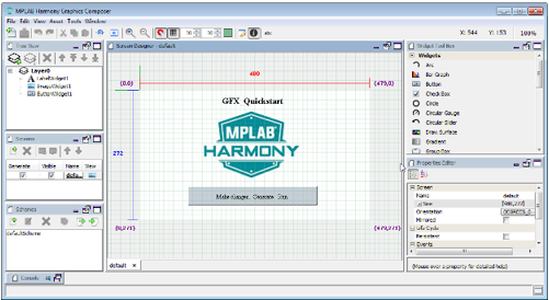
- Select the Graphics Composer from the MHC Pull-Down Menu which will open a new window for the MPLAB Harmony Graphics Composer:
for the MPLAB Harmony Graphics Composer:
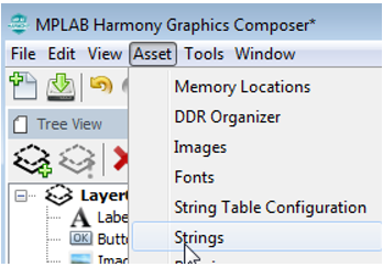
- From the MPLAB Harmony Graphics Composer (MHGC) Asset menu select Strings:
- Add the following strings to the project:
|
Name |
Value |
Font |
|
SAME70_S1 |
“S1” |
TimeNewRoman12 |
|
SAME70_LED1 |
“L1” |
TimeNewRoman12 |
|
SAME70_LED2 |
“L2” |
TimeNewRoman12 |
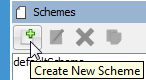
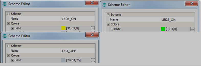
- In the Schemes panel, create three new color schemes:
Call them LED1_ON, LED2_ON, and LED_OFF. Change the Base color of each scheme to be:
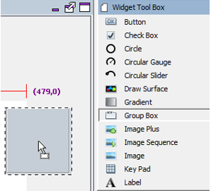
- Drag a Group widget onto the screen:
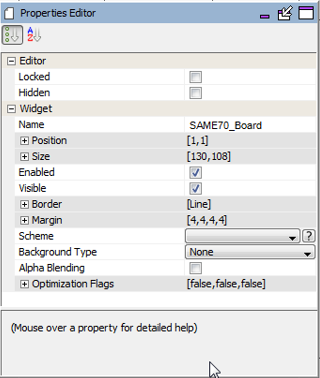
- In the Properties panel for this new widget change the name of the group from GroupBoxWidget1 to SAME70_Board. Change the other properties to be:
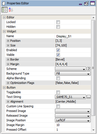
- Drag a Button widget onto the screen. Change its properties to be:
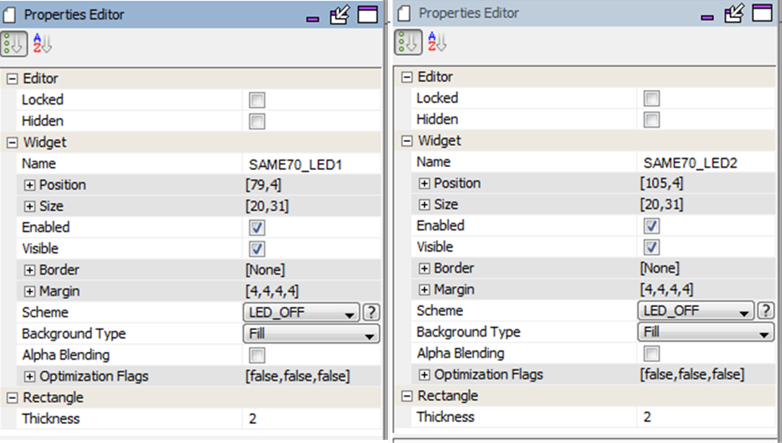
- Drag two Rectangle widgets onto the display to serve as virtual LEDs. Call the first one SAME70_L1 and the second one SAME70_L2. Their properties should be:
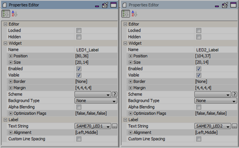
- Finally, drag two Label widgets onto the display to label the two virtual LEDs just added. Call them LED1_Label and LED2_Label. Their properties should be:
- In the Tree View panel organize these new widgets to be part of the SAME70_Board group:
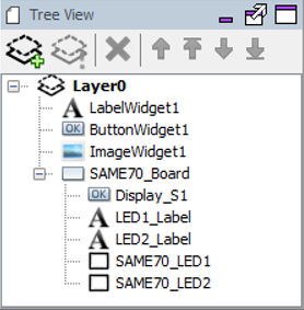
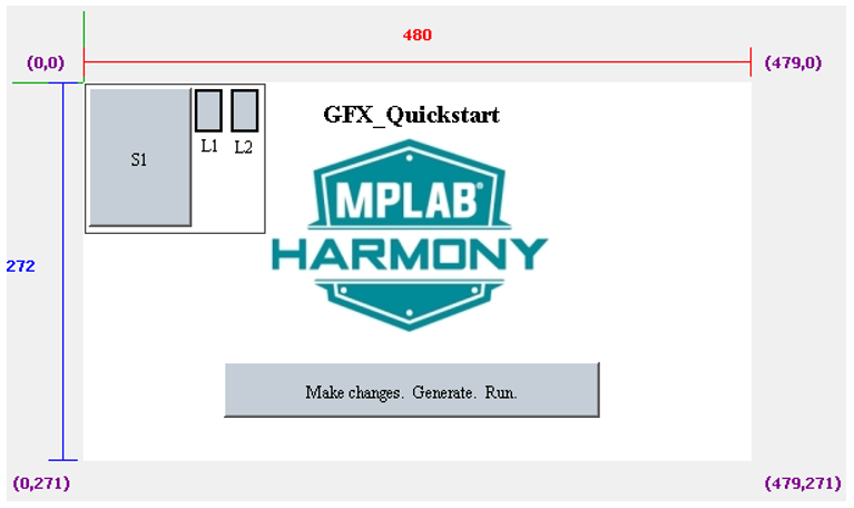
At the end, you should have:
- In the Properties Editor panel for the Display_S1 button, enable both Pressed and Released events:
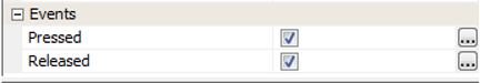
(The contents of the event handlers for these events will be custom coded below.)
- Launch the Events Manager tool from MHGC’s Tools menu.
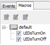
- In the Macros tab, use the Create New Action
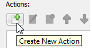
to create two new macros: LEDsTurnOn and LEDsTurnOff.
- Select the LEDsTurnOn macro and then the Create New Action icon:
- In the Action Edit Dialog that next appears, select Next. Select the SAME70_LED1 rectangle widget and then select Next to select the action. Select the Set Scheme action followed by Next. For the Scheme argument select the LED1_ON. Select Finish to return to the Event Manager window.
- Add an action for the SAME70_LED2 rectangle by again selecting the Create New Action icon.
- In the Action Edit Dialog that next appears, select Next. Select the SAME70_LED2 rectangle widget and then select Next to select the action. Select the Set Scheme action followed by Next. For the Scheme argument select the LED2_ON. Select Finish to return to the Event Manager window.
- Select the LEDsTurnOff macro and then the Create New Action icon:
- In the Action Edit Dialog that next appears, select Next. Select the SAME70_LED1 rectangle widget and then select Next to select the action. Select the Set Scheme action followed by Next. For the Scheme argument select the LED_OFF. Select Finish to return to the Event Manager window.
- Add an action for the SAME70_LED2 rectangle by again selecting the Create New Action icon.
- In the Action Edit Dialog that next appears, select Next. Select the SAME70_LED2 rectangle widget and then select Next to select the action. Select the Set Scheme action followed by Next. For the Scheme argument select the LED_OFF. Select Finish to return to the Event Manager window.
- Save the graphics design in MHGC and close the MHGC window.
- Save the MHC state and regenerate the code:
- The libaria_macros.c file (in Source Files > config > lcc_rgb_565_mxt > gfx > libaria ) should now contain:
#include "gfx/libaria/libaria_macros.h"

void LEDsTurnOn(void)
{
    if(laContext_GetActiveScreenIndex() != default_ID)
        return;

    // Set Scheme (SAME70_LED1) - Set Scheme - SAME70_LED1
    laWidget_SetScheme((laWidget*)SAME70_LED1, &LED1_ON);
    // Set Scheme (SAME70_LED2) - Set Scheme - SAME70_LED2
    laWidget_SetScheme((laWidget*)SAME70_LED2, &LED2_ON);
}


void LEDsTurnOff(void)
{
    if(laContext_GetActiveScreenIndex() != default_ID)
        return;

    // Set Scheme (SAME70_LED1) - Set Scheme - SAME70_LED1
    laWidget_SetScheme((laWidget*)SAME70_LED1, &LED_OFF);
    // Set Scheme (SAME70_LED2) - Set Scheme - SAME70_LED2
    laWidget_SetScheme((laWidget*)SAME70_LED2, &LED_OFF);
}
- In the app.h header file add bDisplay_S1State:
// *****************************************************************************
/* Application Data

  Summary:
    Holds application data

  Description:
    This structure holds the application's data.

  Remarks:
    Application strings and buffers are be defined outside this structure.
 */

typedef struct
{
    /* The application's current state */
    APP_STATES state;
    bool bDisplay_S1State;                                                 //New
} APP_DATA;
- In libaria_events.c add support for bDisplay_S1State:
#include "gfx/libaria/libaria_events.h"
// CUSTOM CODE - DO NOT DELETE                                             //New
#include "app.h"                                                           //New
extern APP_DATA appData;                                                   //New
// END OF CUSTOM CODE                                                      //New

// Display_S1 - PressedEvent
void Display_S1_PressedEvent(laButtonWidget* btn)
{
  // CUSTOM CODE - DO NOT DELETE                                           //New
    appData.bDisplay_S1State = true;                                       //New
  // END OF CUSTOM CODE                                                    //New
}

// Display_S1 - ReleasedEvent
void Display_S1_ReleasedEvent(laButtonWidget* btn)
{
  // CUSTOM CODE - DO NOT DELETE                                           //New
    appData.bDisplay_S1State = false;                                      //New
  // END OF CUSTOM CODE                                                    //New
}
27. In app.c make the following changes:
// *****************************************************************************
// *****************************************************************************
// Section: Included Files
// *****************************************************************************
// *****************************************************************************
#include "app.h"
#include "bsp/bsp.h"
#include "gfx/libaria/libaria_macros.h"                                    //New
and
void APP_Initialize ( void )
{
    /* Place the App state machine in its initial state. */
    appData.state = APP_STATE_INIT;
    appData.bDisplay_S1State = false;                                      //New
}
Plus, in APP_Tasks make the following changes:
        case APP_STATE_SERVICE_TASKS:
        {
            bS1State = !SW1_Get(); // Closed --> grounded

            bLED_StateNow = bS1State || appData.bDisplay_S1State;     //Modified
            if ( bLED_State != bLED_StateNow )
            {// LED state has changed
                if ( bLED_StateNow )
                {
                    LED1_On();  // LED1 On
                    LED2_On();  // LED2 On
                    LEDsTurnOn(); // Turn display LEDs on                  //New
                }
                else
                {
                    LED1_Off(); // LED1 Off
                    LED2_Off(); // LED2 Off
                    LEDsTurnOff();   // Turn display LEDs off              //New
                }//end if ( bMEB2_S1State || bDisplay_S1State )
                bLED_State = bLED_StateNow; // Remember new state
            }
            break
        }
- Select the Run Main Project icon to build, load, and run this new configuration.
- Asserting the board’s button should cause the board’s LEDs and the display’s virtual LEDs to light up. Pressing the screen’s virtual button should do the same.
|
MPLAB® Harmony Graphics Suite
|