This tutorial aims to demonstrate how to run MPLAB Harmony Graphics Suite with a third-party capacitive touch display module. For this tutorial, we will use a Mikroe TFT Proto 5” Capacitive display module that is connected to a PIC3MZ EF Starter Kit. The display module has an 800x480 resolution display with an SSD1963 display controller, and a FT5306 capacitive touch controller.
This tutorial requires knowledge of how to create an MPLAB Harmony project and using MPLAB Harmony Graphics Composer to design a screen. These processes won’t be covered in this tutorial.
1. Create an MPLAB Harmony Project for the PIC32MZ2048EFM144. Make sure to include the gfx package when creating the project.
2. In the MPLAB Harmony Configurator, add and connect the components as shown in the Project Graph below.
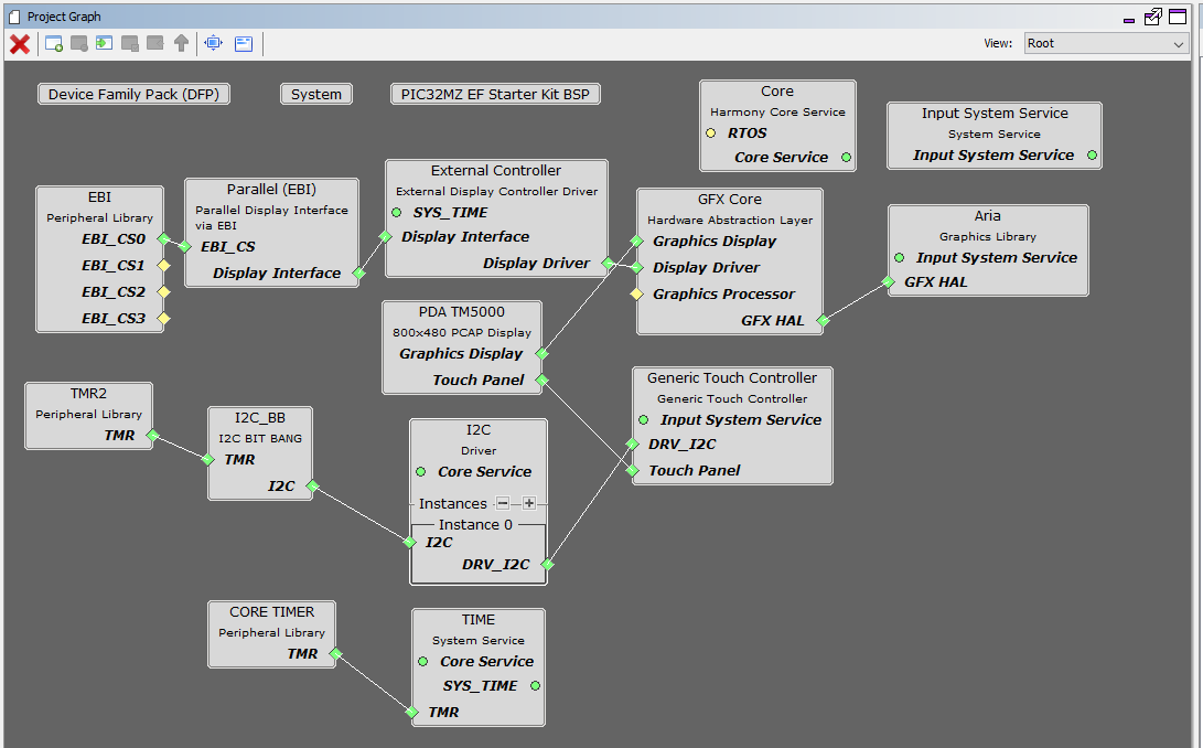
3. Next, set the configuration options in the following components in the Project Graph
- EBI Peripheral Library
- Parallel (EBI) Display Interface
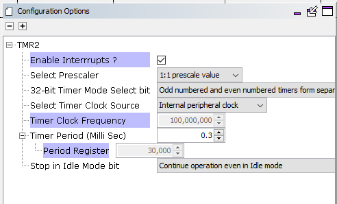
- TMR2 Peripheral Library
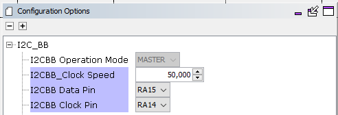
- I2C_BB, I2C Bit Bang
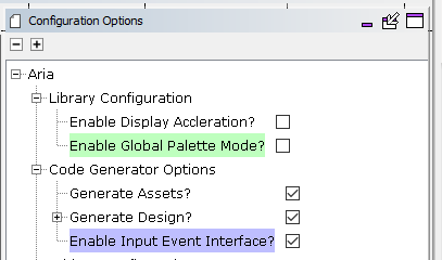
- Aria Graphics library
4. In the MHC Project Graph, select and configure the External Controller component to generate a driver for the SSD1963 display controller on the display module.
The External Controller component can generate a driver for class of controllers that have the following properties:
• Supports SPI 4-line or Parallel (16- or 8-bit) 8080 interface
• Supports command + data writes for controller setup and frame data
• Supports frame data write using Column/Row addressing
• Supports 16-bit RGB565 color mode
Examples of controllers that are supported are the ILI9488, SSD1963, ST7796S and SSD1351.
To start configuring the driver generator for SSD1963,
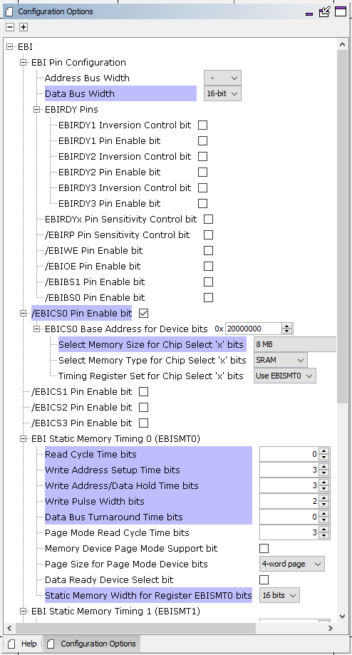
- Set the Display Interface Type to Parallel 8080
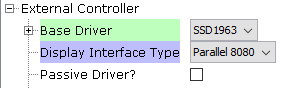
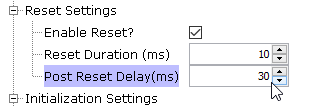
- Under Reset Settings, set the Post Reset Delay(ms) to 30. This adds a 30ms delay after the reset signal is asserted, before the MCU starts communicating with the display controller.
- The Initialization Settings lets you specify the commands and parameters that will be sent to configure the display controller.
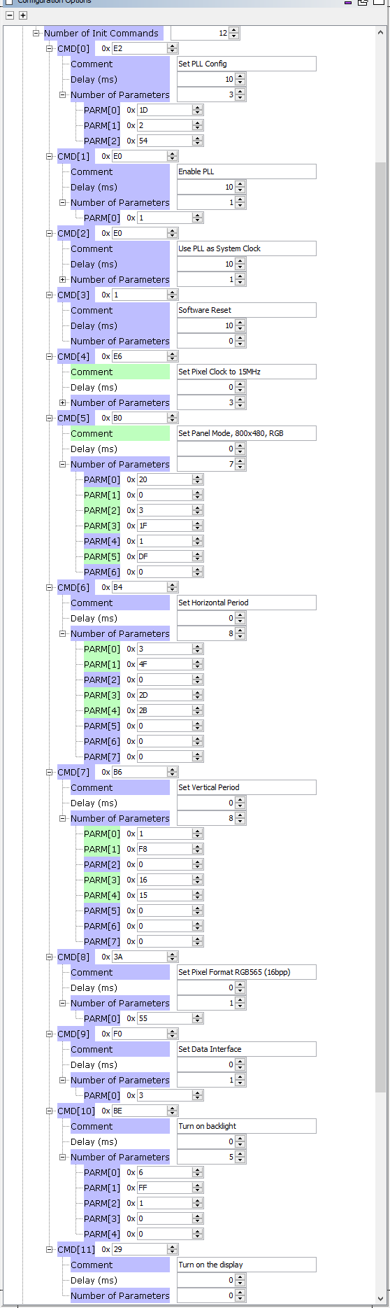
To configure the SSD1963 display controller to drive the display at the right timing and resolution, 12 sets of commands and parameters are needed. Set the Number of Init Commands to 12, and fill out the options for the commands and parameters as shown below. A Comment option is set to describe what the command does.

- Next, the Pixel Transfer Function options must be set. The Pixel Transfer Function sends the command and parameter set to write or read pixel data on the display controller.
The Pixel Data Settings configures the driver based on the format of the pixel data. The Pixel Data Transfer Size is set based on the width of the pixel data frame thru the display interface. In the case of this tutorial, we are using a 16-bit wide parallel interface.
![]()
The position of the pixel is set using the Set Column/X and Set Page/Y commands and the parameters of these commands are the X and Y addresses. The values for these commands for the SSD1963 are set with the size of the address parameter as 2-bytes.
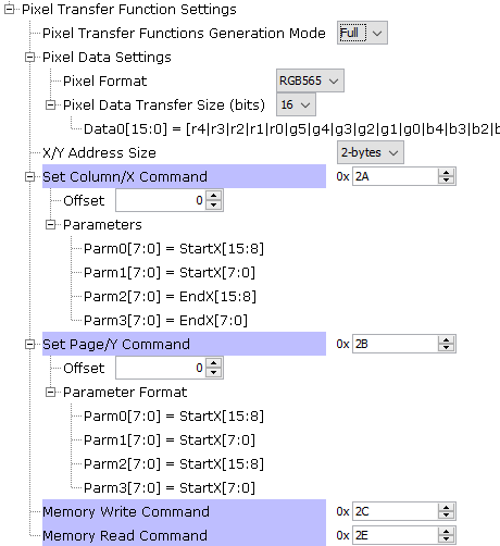
The value of the commands for writing and reading pixel data in the SSD1963 display controller memory are set.
Note: For controllers that require a pixel transfer function/protocol that cannot be generated by the driver generator, the driver generator can be configured to generate stub or empty pixel transfer functions. In this case, the user will need to complete the function definition in the generated driver file. Set the Pixel Transfer Functions Generate Mode to Stub for this case.
![]()
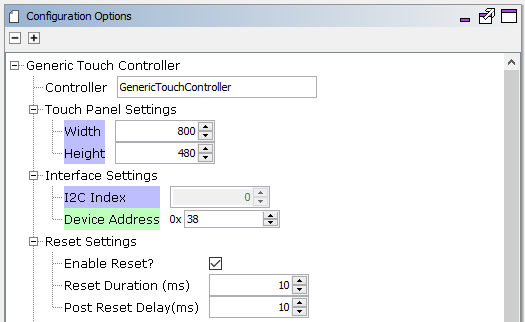
5. In the MHC Project Graph, select and configure the Generic Touch Controller component to generate a driver for the FT5306 capacitive touch controller on the display module
The Generic Touch Controller can generate a driver for a class of touch controllers with the following properties:
• Uses I2C interface for configuration and reading touch data
• Asserts a GPIO signal to the host MCU for valid touch data
• Uses command + data writes for controller setup
• Bytes/Frame containing touch event type and position values have fixed offsets in the touch data
Examples of controllers that are supported are the FT5306 and FT5426.
To configure the driver generator for FT5306,
a. Set the touch resolution.
b. Set the I2C interface settings. The FT5306 I2C slave address is set to 0x38.
c. The default Reset Settings are used.
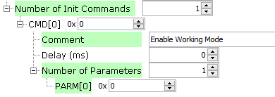
d. Next, the initialization command(s) are set. In the case of the FT5306, the device only needs to be set to Working Mode by writing 0x0, 0x0 over the I2C bus.
e. Next, the Touch Event Settings are set.
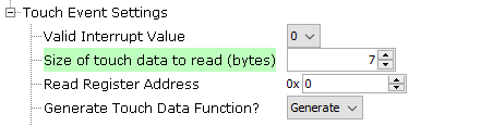
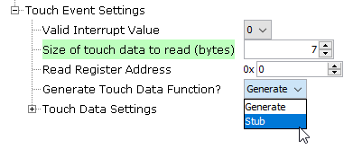
The FT5306 pulls to low (0) the INT signal when a valid touch event is detected. The Valid Interrupt Value is set to 0 so the driver will start reading the touch data when the INT signal is low.
We will use the Register Map of the FT5306 as reference for configuring how to read and interpret the touch data.
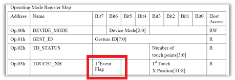
The Register Map indicates that the touch event and touch position is contained in the first 7 bytes of data that is read from address 0. So the driver is configured to read 7 bytes (Size of touch data to read) starting at address 0x0 (Read Register Address).
f. Next, the Touch Event must be extracted and interpreted from the Touch Data.
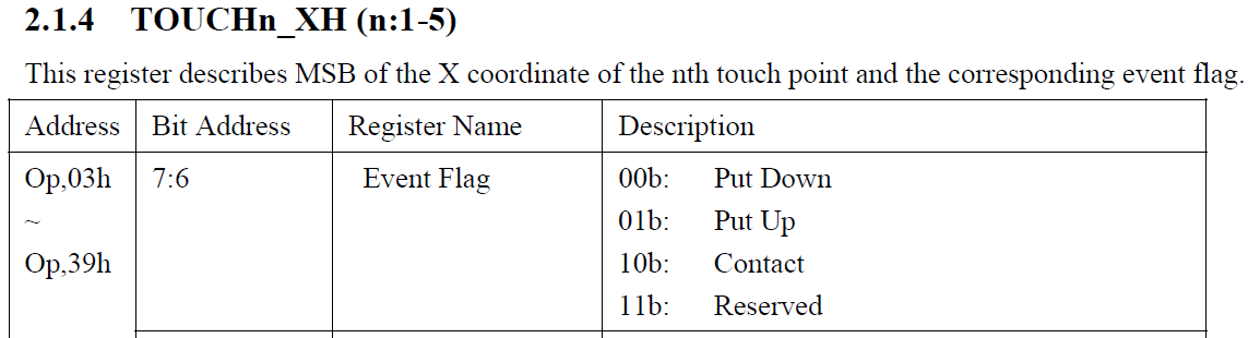
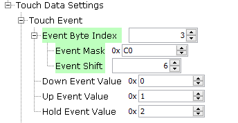
Based on the Register Map, the Touch Event type is in Address/Byte 3, bits 7 & 6. To extract the value of the Touch Event, Byte 3 (Event Byte Index) must be masked with 0xc0 (Event Mask) and shifted 6 (Event Shift) bits to the right.
The value of the touch event is to be interpreted as follows:
Given this information, the Touch Event options are configured as follows:
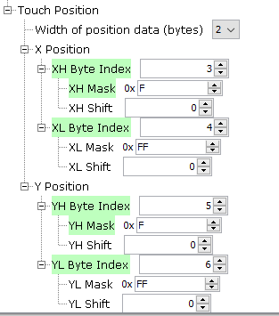
g. Next, the Touch Position needs to be extracted from the Touch Data. Based on the FT5306 register map, the X and Y positions are 2-bytes long.
The upper byte of the X position is in byte 3, and lower byte in byte 4. Bytes 5 and 6 contains the upper and lower bytes of the Y position.
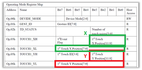
With this, the X and Y Position options are set as follows:
Note: For controllers with touch data format that cannot be supported by the touch driver generator, the driver generator can be configured to generate stub or empty touch data processing function. In this case, the user will need to complete the definition of the drv_touch_process_data() function in the generated driver file, drv_touch_controller.c.
Set the Generate Touch Data Function option to Stub for this case.
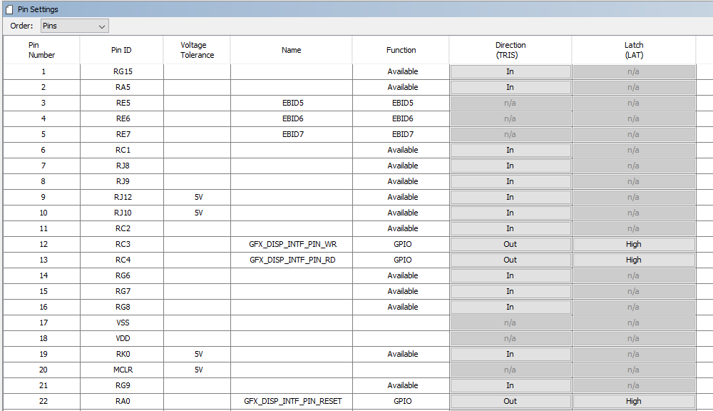
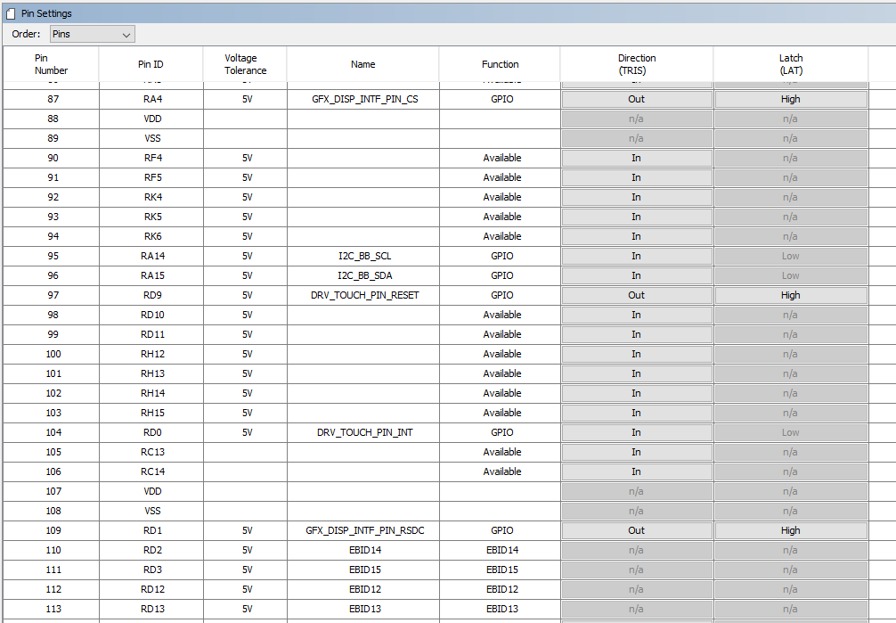
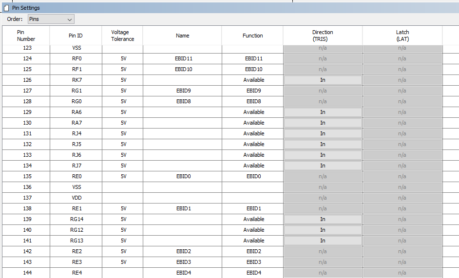
6. Next, the pins used to interface with the display module need to be configured in MHC Pin Settings.
The table below lists the PIC32MZ EF that are used to drive the LCD and Touch signals to the display module.
|
Signal |
MCU Pin # |
MCU Pin ID |
Name |
Function |
Direction |
Latch |
|
TFT-D5 |
3 |
RE5 |
EBID5 |
EBID5 |
|
|
|
TFT-D6 |
4 |
RE6 |
EBID6 |
EBID6 |
|
|
|
TFT-WR# |
6 |
RE7 |
EBID7 |
EBID7 |
|
|
|
TFT-WR# |
12 |
RC3 |
GFX_DISP_INTF_PIN_WR |
GPIO |
Out |
High |
|
TFT-RD# |
13 |
RC4 |
GFX_DISP_INTF_PIN_RD |
GPIO |
|
High |
|
TFT-RST# |
22 |
RA0 |
GFX_DISP_INTF_PIN_RESET |
GPIO |
Out |
High |
|
TFT-CS# |
87 |
RA4 |
GFX_DISP_INTF_PIN_CS |
GPIO |
Out |
High |
|
CTP-SCL |
95 |
RA14 |
I2C_BB_SCL |
GPIO |
In |
|
|
CTP-SDA |
96 |
RA15 |
I2C_BB_SDA |
GPIO |
In |
|
|
CTP-RST# |
97 |
RD9 |
DRV_TOUCH_PIN_RESET |
GPIO |
Out |
High |
|
CTP-INT# |
104 |
RD0 |
DRV_TOUCH_PIN_INT |
GPIO |
In |
|
|
TFT-D/C# |
109 |
RD1 |
GFX_DISP_INTF_PIN_RDSC |
GPIO |
Out |
High |
|
TFT-D14 |
110 |
RD2 |
EBID14 |
EBID14 |
|
|
|
TFT-D15 |
111 |
RD3 |
EBID15 |
EBID15 |
|
|
|
TFT-D12 |
112 |
RD12 |
EBID12 |
EBID12 |
|
|
|
TFT-D13 |
113 |
RD13 |
EBID13 |
EBID13 |
|
|
|
TFT-D11 |
124 |
RF0 |
EBID11 |
EBID11 |
|
|
|
TFT-D10 |
125 |
RF1 |
EBID10 |
EBID10 |
|
|
|
TFT-D9 |
127 |
RG1 |
EBID9 |
EBID9 |
|
|
|
TFT-D8 |
128 |
RG0 |
EBID8 |
EBID8 |
|
|
|
TFT-D0 |
135 |
RE0 |
EBID0 |
EBID0 |
|
|
|
TFT-D1 |
138 |
RE1 |
EBID1 |
EBID1 |
|
|
|
TFT-D2 |
142 |
RE2 |
EBID2 |
EBID2 |
|
|
|
TFT-D3 |
143 |
RE3 |
EBID3 |
EBID3 |
|
|
|
TFT-D4 |
144 |
RE4 |
EBID4 |
EBID4 |
|
|
These pins are set to the corresponding Name, Function, Direction and Latch values in the MHC Pin Settings.
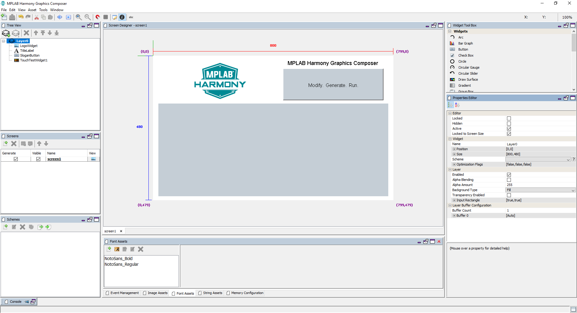
7. Next in MHC, launch Tools -> Graphics Composer to design the screen. Here’s the sample design that adds image, label, button and touch test widgets to the screen.
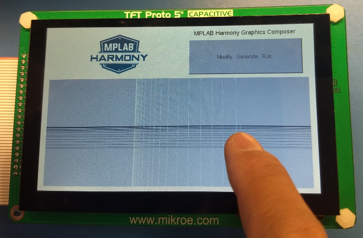
8. When done composing the screen, go back to MHC and generate the project code. Compile and Run the code on the target to see the screen on the display. The widgets on the screen should respond to touch events when touched.
|
MPLAB® Harmony Graphics Suite
|